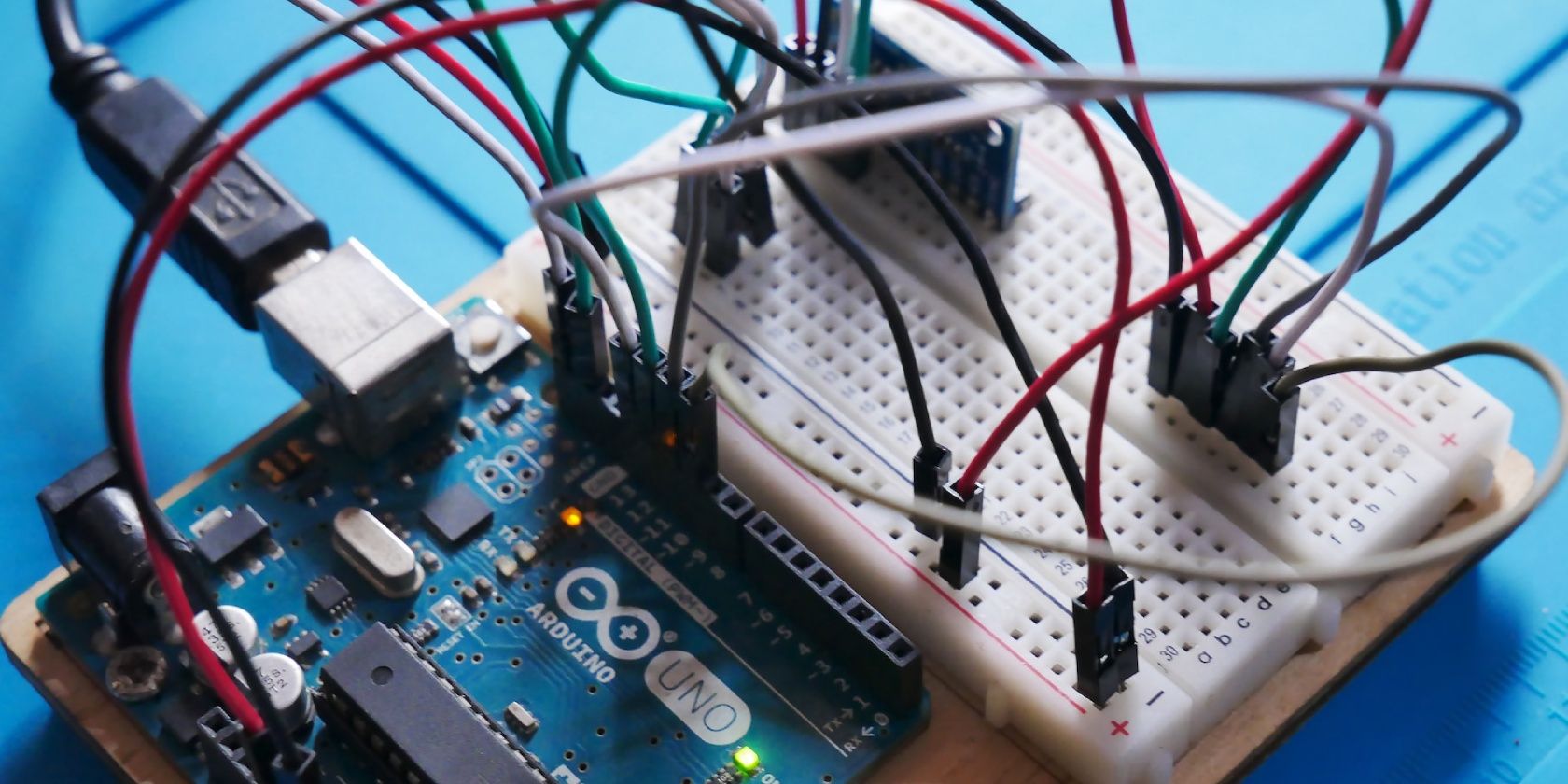
Solderless breadboards are ideal for circuit prototyping, providing a platform for quick and flexible experimentation. However, to ensure the success of circuit designs, accurate measurement of voltage across components on the breadboard is very helpful. Let's take a look at how to measure voltage on a breadboard.
What Is Voltage?
Voltage, often referred to as electric potential difference, is the driving force that powers our electrical circuits. Its unit of measurement is volts (V) and this represents the potential energy difference between two points in a circuit, similar to the difference in water pressure between two ends of a pipe.
Voltage Measurement Instruments
There are two primary instruments commonly used to measure voltage:
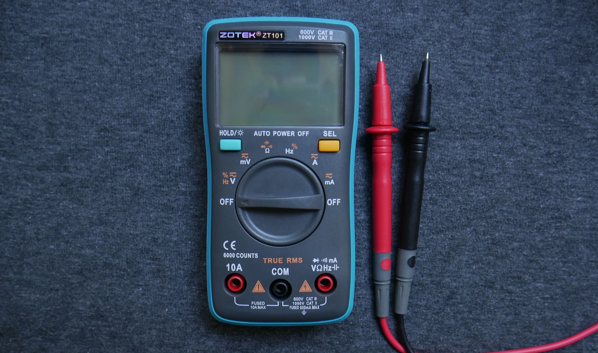
Digital Mulitmeter (DMM)
The digital multimeter is a standard diagnostic tool used to measure voltage, current, and resistance. Analog voltmeters with needles have long been supplanted by digital multimeters due to their increased accuracy, and reliability.
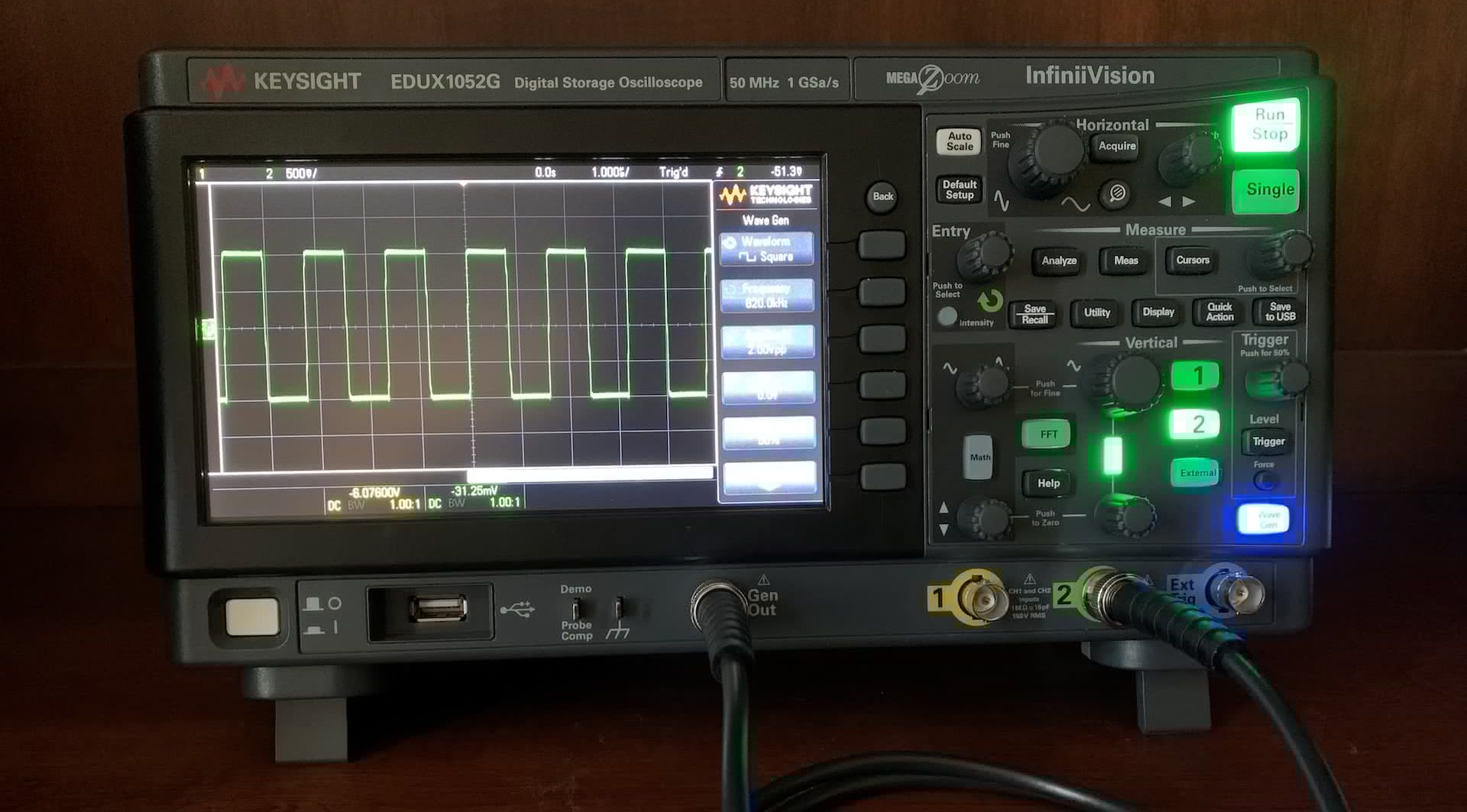
Oscilloscope
The digital oscilloscope is a valuable tool for analyzing dynamic electrical signals with complex waveforms. It provides a visual representation of voltage variations over time, making it useful for examining electronic signals in your projects.
Connecting Components to the Breadboard
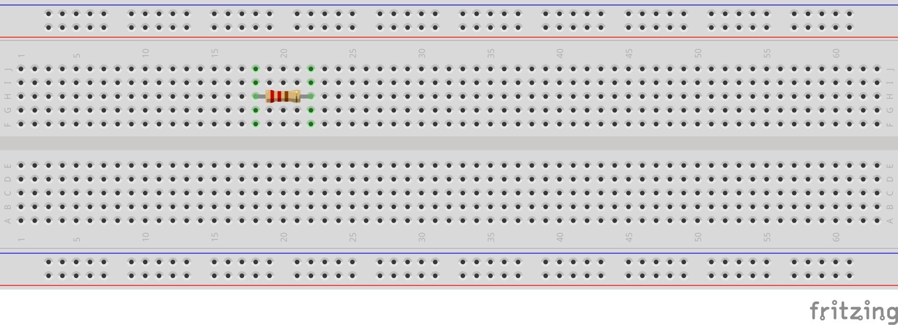
Connecting standalone electronic components is easiest. All you have to do is to identify the desired rows and insert the two terminals of the component, e.g. a resistor, in different vertical rows of the inner part of the board. Just make sure that the leads touch the metal plates underneath the holes on the breadboard.
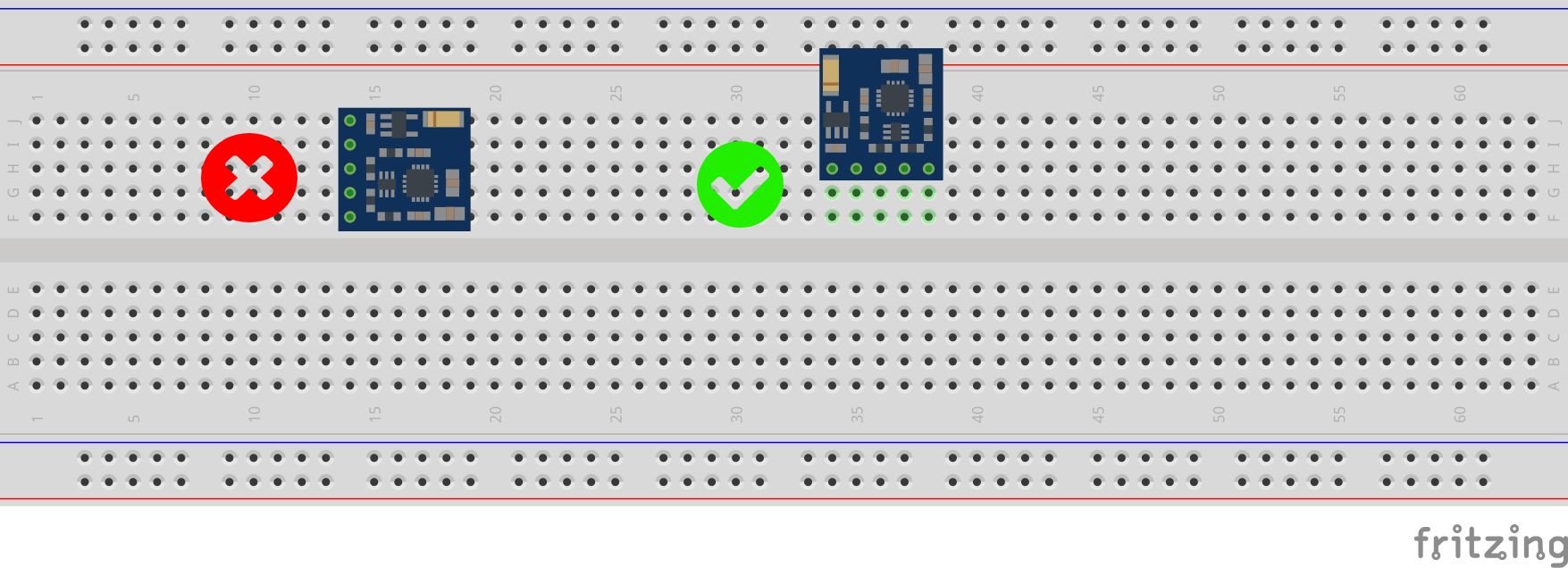
When connecting circuit boards to the breadboard, just make sure you don’t short-circuit the leads. This is pretty common if you are new to circuit fabrication on a breadboard with small modules. Here is a perfect demonstration of this.
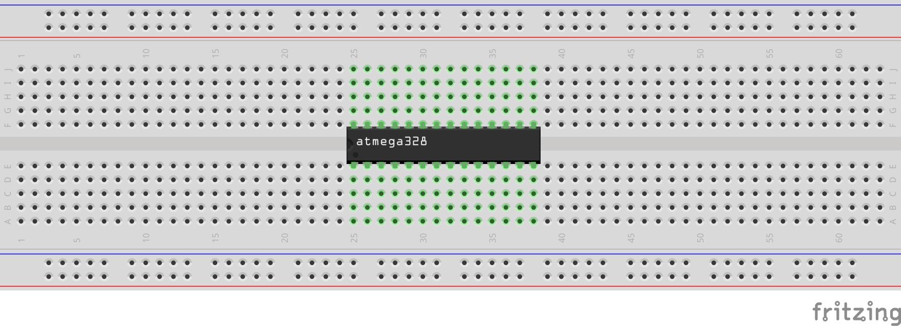
When connecting ICs, always make sure you place it astride the center bridge that separates the two inner sections of the breadboard.
Jumper wires also have to be inserted all the way in to make sure you don’t get any loose connections.
Power and Ground Rails
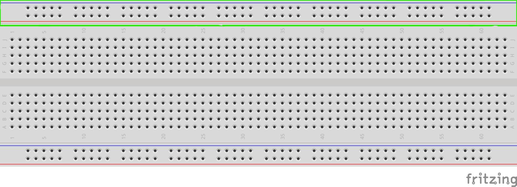
Breadboards typically feature two long metal strips running along the edges of the board. These are known as power and ground rails and serve specific purposes in circuit design.
The power rail, often denoted by red markings or the symbol "+," is used to supply voltage to the components. It is commonly connected to the positive terminal of the power source or the voltage supply within the circuit.
The ground rail, typically marked with blue markings or the symbol "-", provides a reference point for the circuit's electrical potential. It connects to the negative terminal of the power source and acts as the common ground for the components. For more details, check out what a breadboard is and how to use one.
Measuring Voltage Across Components
One of the key objectives in circuit analysis during fabrication on a breadboard is to measure the voltage at specific nodes and across components in the circuit. This helps you understand the dynamics of whatever circuit you are fabricating.
Standalone Components
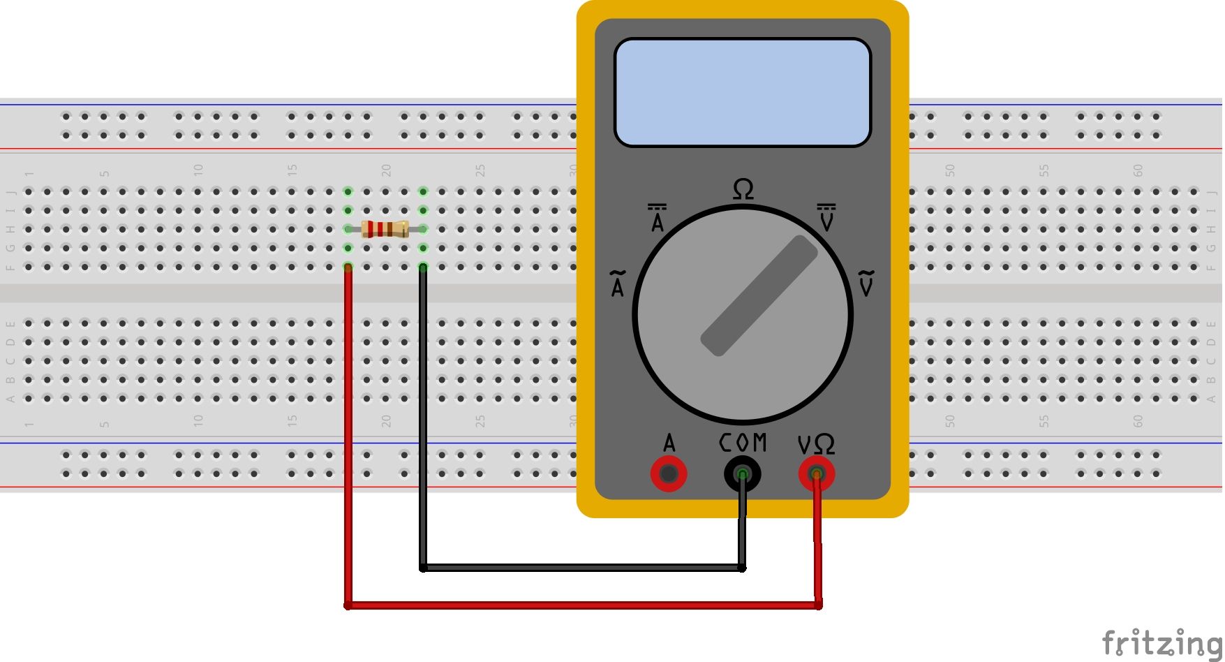
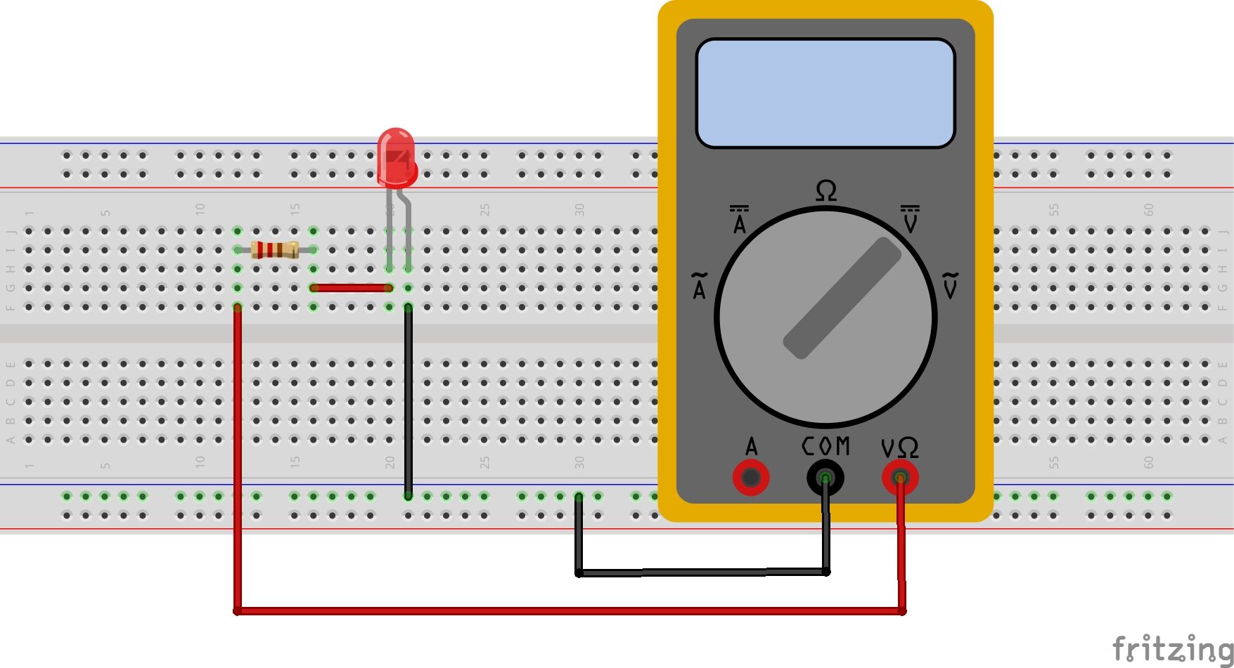
When measuring the voltage across standalone components, you just need to set the multimeter to the right setting and get the probes right. Some components, such as LEDs, have a set polarity; others, like resistors, do not. The diagram below show how to measure the voltage drop across a resistor with a voltmeter/multimeter.
Junctions or Nodes
To measure the voltage at a junction or node in a circuit, just locate the ground reference of the circuit and the junction itself.
Note that if your circuit has a floating ground, you may get inaccurate readings or no reading at all.
Series Components
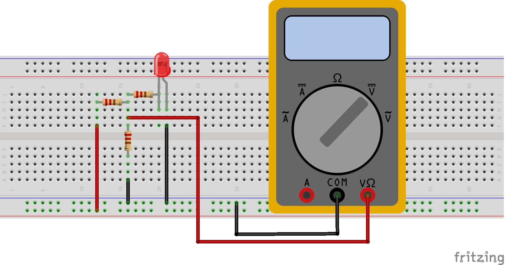
For components connected in series, make sure you have the probes of the multimeter (or oscilloscope) at the extreme ends of the circuit, as shown below.
Power Rails
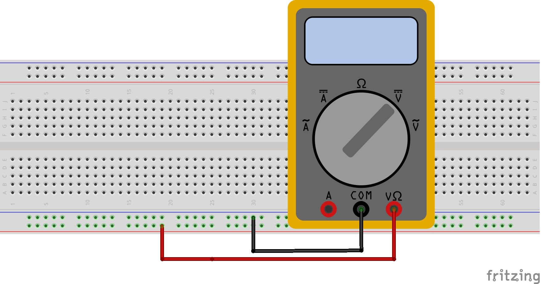
The voltage across the power/ground rails is pretty straightforward as you only have to use the two rails, positive and negative, to take the measurement. Make sure you connect the red probe to the rail that is connected to a power source.
Common Mistakes During Measurement
To ensure accurate measurements and prevent potential damage to components on a breadboard, it is crucial to be aware of common challenges.
1. Not Splitting 3.3V and 5V Power Rails
When working with circuits that require both 3.3V and 5V power sources, you should split the power rails on the breadboard. This prevents unintentional connections between the different voltage levels, minimizing the risk of damaging components. You can use the top rail for 5V and the bottom rail for 3.3V
2. Not Bridging the Power Rails
Some breadboards have a breaking bridge that splits the power rails into two halves. This can be easily solved by bridging the rails for continuity.
3. Using AC Power on DC Components
AC power can cause severe damage to DC components, including integrated circuits and microcontrollers. In case you really need to, always use coupling capacitors for DC isolation—a common method for amplifier design on breadboards.
Know the Right Way to Measure Voltage
Understanding how to accurately measure the voltage across components on a breadboard is an essential skill for successful circuit prototyping. By grasping the concept of voltage and following proper measurement techniques, you gain the power to optimize your circuit designs and ensure reliable performance.

