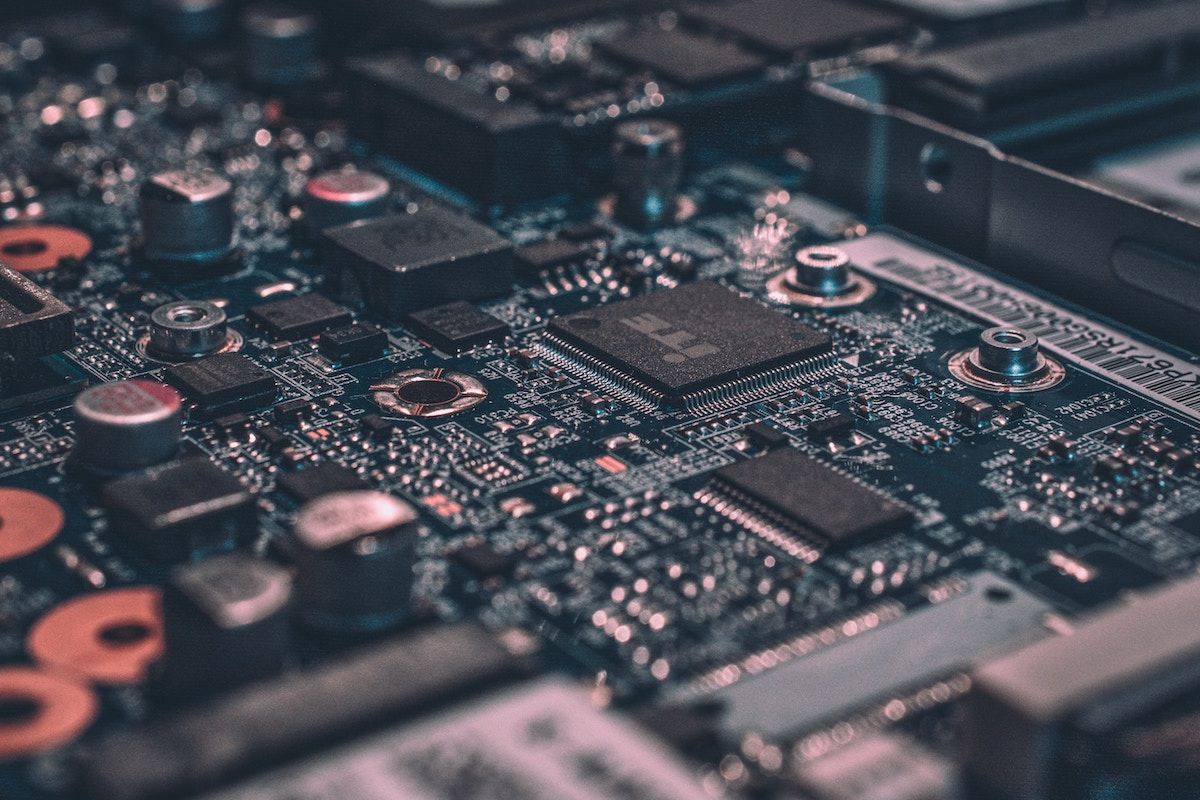
For most PC enthusiasts, choosing the right motherboard involves key considerations such as form factor, CPU compatibility, memory configuration, connectivity options, and overclocking headroom. However, one major motherboard component that often goes unnoticed, even in a spec sheet, is its VRM (voltage regulator module)—an electronic circuit responsible for ensuring a system's overall stability.
To assess the importance of this underappreciated switching regulator, let's delve right into the functioning of a VRM, the components associated with it, how to differentiate between a high-quality and poorly engineered VRM, as well as its impact on CPU performance.
How Does a VRM Work?
At its core, the voltage regulator module on your motherboard (also referred to as the processor power module) is a specialized buck converter (DC to DC) that regulates and converts voltages to align with the specific requirements of the CPU, memory, and other components. Think of VRMs as mini power supplies, akin to the main unit, which takes 120 or 240V AC from the electrical outlet and steps it down to a much lower DC voltage (12V/5V/3.3V).
In this regard, motherboard VRMs perform the same operation as the PSU, but on a secondary level. Their primary objective is to convert the incoming 12V from the 8/4-pin EPS connectors into a suitable operating voltage for modern CPUs (typically in the range of 1.1-1.5V).
Moreover, VRMs are pivotal in transmitting clean and consistent voltage to every power-hungry component in your PC, reducing the likelihood of any absurd surges or VDroops. Owing to their steady conversion capabilities, voltage regulation circuits also allow multiple generations of CPUs (with dynamic core voltage) to function optimally on a compatible motherboard chipset.
Components of a VRM
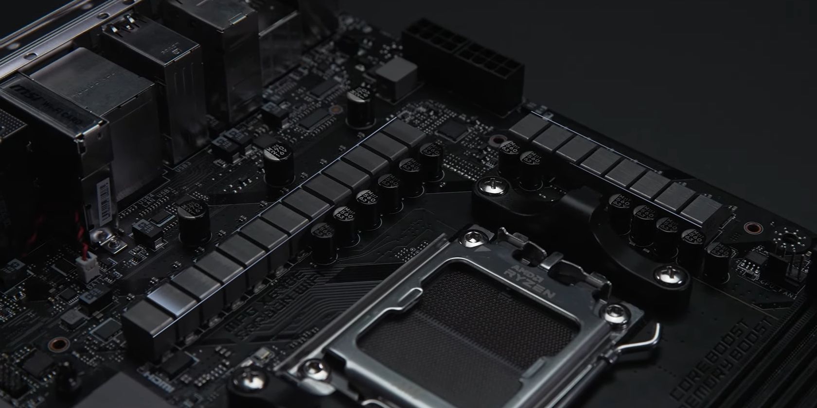
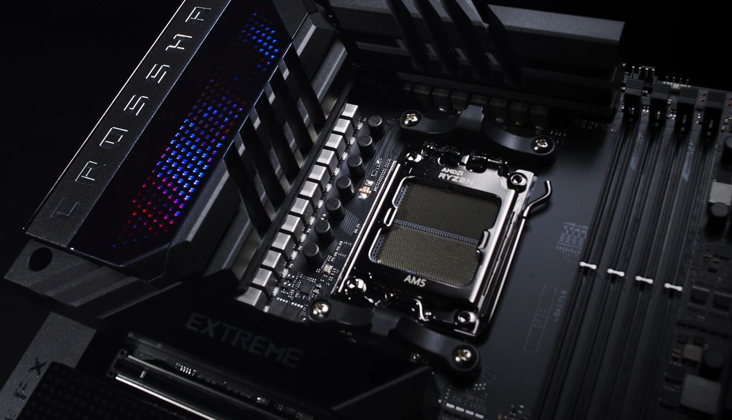
While many of us consider the VRM an independent, self-contained unit, the acronym represents a collection of distinct electronic components surrounding the CPU socket (LGA or PGA) and DIMM slots on our motherboard. For those uninitiated, voltage regulation circuits incorporate a combination of MOSFET switches that work in tandem with capacitors, chokes, and PWM controllers to facilitate the power phasing process.
Here's a comprehensive overview of all the essential components constituting motherboard VRMs.
1. MOSFETs
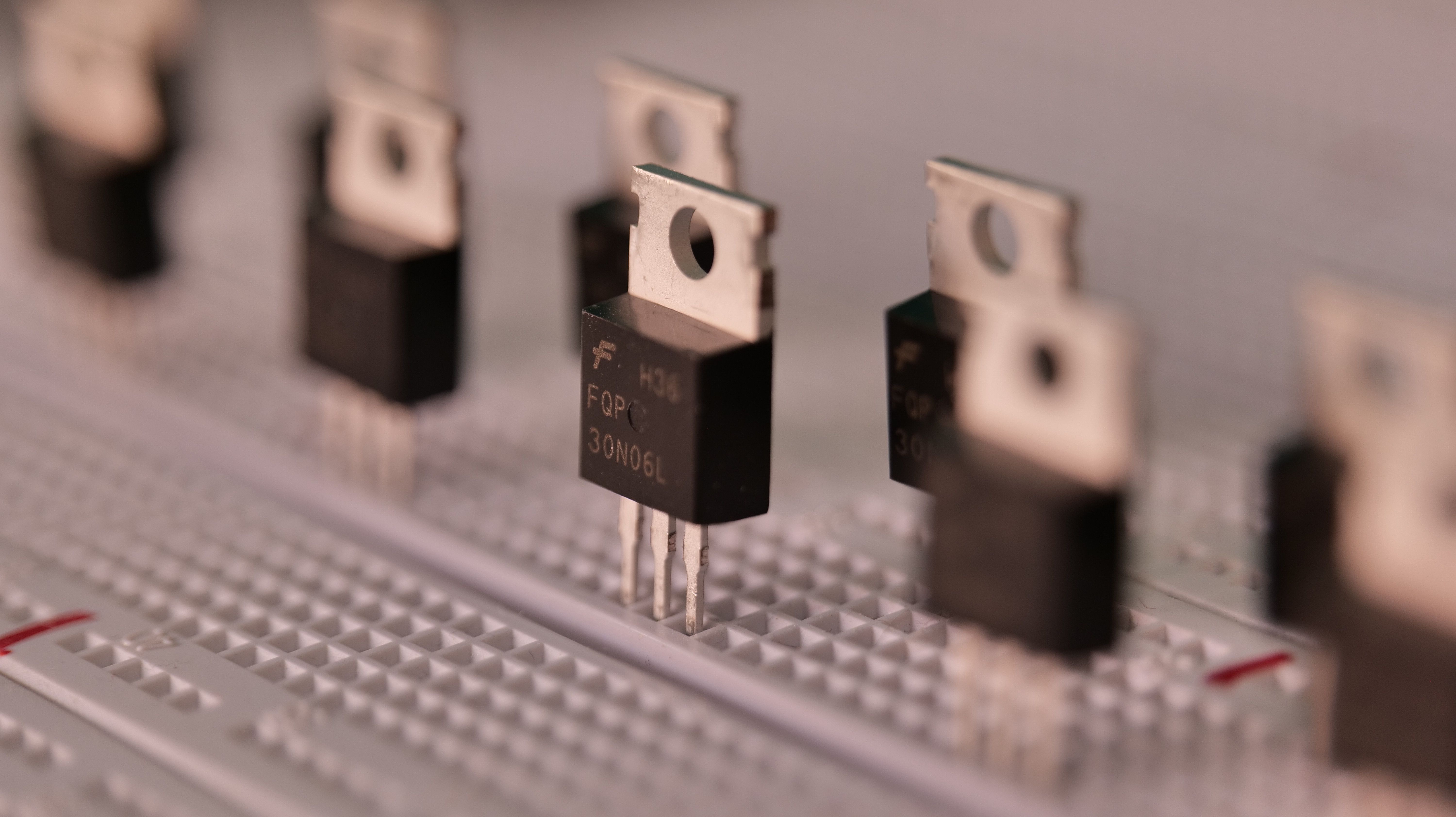
MOSFETs (Metal-Oxide-Semiconductor Field-Effect Transistors) act as insulated gates that amplify or attenuate electronic signals within a voltage regulation circuit. In simpler terms, these semiconductors control the flow of current to the CPU based on signals and values received from the PWM controller chip.
A single-phase VRM employs two MOSFET switches (low-side and high-side) to assist in modulating the average output voltage of a circuit by intermittently toggling an input voltage. Since the switching mechanism occurs hundreds of times per second, MOSFETs tend to generate a large amount of heat, with temperatures that can potentially exceed 150°C under heavy loads or without adequate cooling.
As a result, these semiconductors are often equipped with passive heat sinks, miniature fans, or water blocks to mitigate overheating issues and improve operational efficiency.
2. Chokes
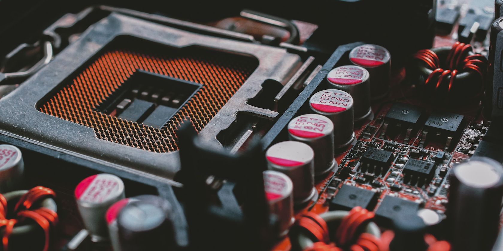
Chokes are cubic-shaped inductors that transform high-frequency AC signals into lower frequencies or direct currents within a voltage regulation circuit. Featuring a donut-shaped magnetic core with an insulated coil wrapped around it, this electronic device serves a dual purpose—storage, filtration, and refinement of power and the ability to regulate power delivery in extreme scenarios like overclocking or overvolting.
Furthermore, it should be noted that each choke corresponds to a power phase on your motherboard. The higher the number of phases, the more stable will the voltage transmission be to your CPU.
3. Capacitors
Unlike chokes, capacitors store energy within an electric field and rapidly discharge the accumulated current into connected circuits when necessary. The main purpose of these cylindrical components is to prevent sudden voltage spikes and minimize ripples in a voltage regulation circuit.
In the context of motherboard VRMs and their corresponding phases, capacitors, functioning as temporary storage units, amass the electric current received from the chokes and deliver the requisite power to your CPU. Any excess charge from these devices gets absorbed or released via the circuit ground.
4. PWM Controllers
PWM (pulse width modulation) controllers or Driver ICs (integrated circuits) generate PWM pulses, which are subsequently channeled into the core analog components of a voltage regulation circuit—MOSFETs and chokes. Besides monitoring, these multi-phase controllers dynamically adjust power delivery to the CPU, allowing it to maintain peak efficiency during intensive workloads.
In essence, the PWM controller acquires the reference voltage of your CPU (also referred to as VRef within the BIOS) and measures it with the prevailing voltage from your motherboard's VRM. Any differences between the VRef and actual voltage prompt this device to recalibrate the signals, modulating the output voltage instantaneously.
The core components of a VRM are also complemented by diodes and resistors, which safeguard against electric current flowing into these devices from surpassing specified thresholds.
Multi-Phase VRMs on a Motherboard
Modern CPUs and GPUs require a robust power delivery system, which extends beyond the mere capabilities of a single-phase VRM. To achieve a relatively stable and efficient transmission procedure, motherboard manufacturers almost always incorporate multiple buck converters in parallel, creating a multi-phase VRM solution.
For starters, the staggered arrangement of a multi-phase VRM setup divides the load into separate power stages, distributing it across a wider physical area. This sophisticated power management approach provides the CPU with a clean and precisely regulated operating voltage and curtails heat generation and stress within the core components.
When shopping for a brand-new motherboard, you'll likely encounter the phase power design terminology in its marketing material, indicating the allocation of phases to the PCB (printed circuit board). This specification is often touted by manufacturers in an "A+B" (8+2) or "X+Y+Z" (16+2+2) format—the initial value preceding the "+" sign signifies the number of phases dedicated to the CPU, whereas the combination following the plus sign pertains to other critical components on a motherboard. (RAM, Chipset, iGPU, etc.).
However, in instances where the actual number of phases reserved for the CPU exceeds eight, as seen in designations like "18+2" or even higher, motherboard manufacturers tend to include a tricked-out device called a doubler. Simply put, VRM doublers allow manufacturers to split the control signals for a phase, effectively doubling the number of phases from a control standpoint. However, the benefits might not be as significant as true additional phases.
Moreover, the inclusion of doublers within a "True" 8-phase VRM setup yields significant improvements to the power phasing process at a lower manufacturing cost.
How to Differentiate Between a High-Quality and Poorly Engineered VRM Configuration?
Several factors come into play when evaluating motherboards based on the quality of their VRM configurations. Even if you aren't planning to overclock your CPU, a poorly designed VRM solution can ruin the power delivery mechanism by a considerable margin, leading to system instability, crashes, BSODs, and other glaring issues.
Here's how to differentiate between a top-tier VRM configuration and one that falls way short of expectations.
- Phase Power Design: One of the easiest methods to determine the quality of a VRM configuration is to physically inspect the total number of chokes visible on your motherboard. For an entry-level chipset like the AMD A620, you should be able to locate a maximum of four to six power phases concealed underneath a heat sink. In contrast, a mid-range or high-end motherboard takes advantage of a much larger phase count for handling power-hungry components.
- Leak-Resistant Capacitors: High-quality VRMs utilize solid-state capacitors, often marketed as "Japanese Capacitors," "Dark Capacitors," or "Hi-C caps." Compared to their electrolytic counterparts, solid capacitors have a much higher tolerance rate and are less prone to aging.
- Premium Alloy Chokes: We recommend investing in a motherboard that employs SFCs (Super Ferrite Chokes) or Premium Alloy Chokes as they consume less power, resist corrosion, and generate lower electromagnetic interference.
Of course, inspecting a motherboard before purchasing isn't easy. However, you can always give it a good look over when it arrives, then send it back if it's not up to scratch.
Motherboard VRMs: The Unsung Hero of Modern Computing
Fundamentally, the concept of a VRM can be quite intricate as it involves a plethora of technical jargon (MOSFETs, chokes, capacitors, PWM controllers, etc.) that might be unfamiliar to the average PC enthusiast. Despite such complexities, motherboard VRMs serve as the backbone for efficient voltage transmission to the CPU and other essential components in your PC.

